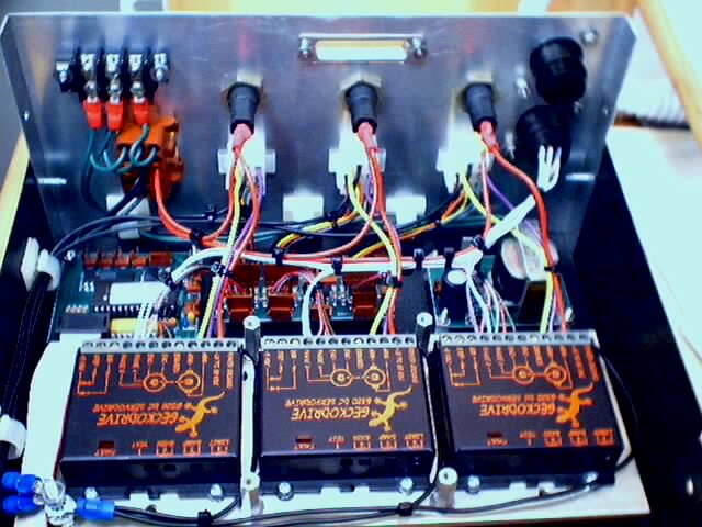
Here's a couple of pictures of my controller.
The brown connector on the left of the rear panel goes to the power supply. To keep things neat, I put the power supply in an external chassis.
The hole in the middle is for a small PCB with the DSub for connection to the PC. I've left it out as it obscures things.
The round black connectors on the right are circular "MIL" style connectors. The bottom connector goes to a DRO. Since my Shoptask has ballscrews with double ball nuts on it for pretty low lash and pretty good repeatability, I thought I'd use the encoders on the motors. Beats setting and reading the mechanical dials.
The empty black connector on the top goes to the DSub on the inside and the various limit switches on the outside.
In between the Geckos and the back panel are ( from left to right ) the PIC Error/Reset controller PCB, the Differential Receiver PCB and a small 5 volt power supply PCB.
Not shown are the relays. They mount on a separate plate that then attaches to the standoffs surrounding the middle Gecko.
Note in the lower left the #8 bolt that acts as a single point ground for the whole system. EVERY ground from every board or device goes back to this single point.
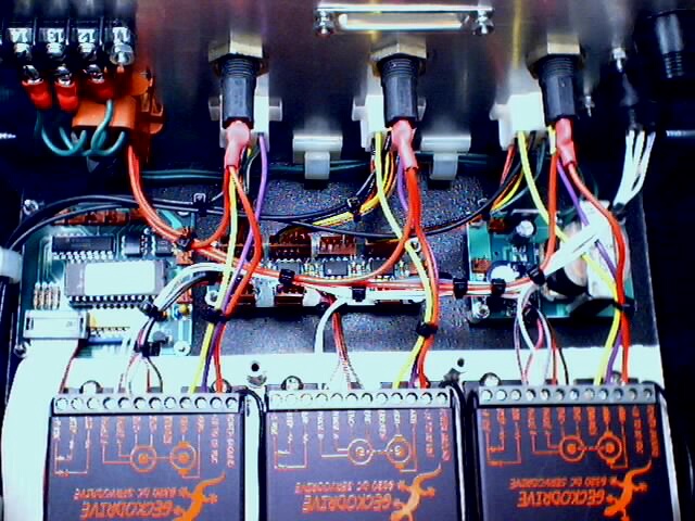
Another view of the wiring.