Such noise is almost invariably introduced by the nature of the signals coming from the encoders. They are standard logic level signals, and as such, were never intended to be sent long distances and were certainly never intended for use in the sort of noisy environment presented by a typical machine shop.
The solution, though, is simple and well understood - drive the signals differentially to a low impedence input. I don't want to get too technical here with why this works. Suffice it to say that this is the way all such signals are transmitted in an industrial environment and cheap, standard chips have been around for a long time to do exactly what we need.
Here's my solution to the "problem".
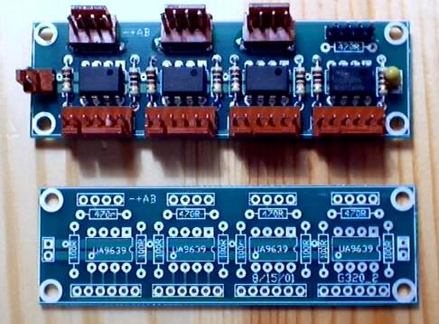
This is the board at the controller end, the receiver board.
The bottom of the boards have the inputs, the top shows the outputs, wired for direct connection to the Geckos.
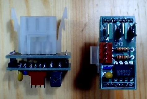
Here's the transmitter board(s), to be used at the motor.
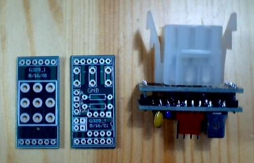
They are designed to be soldered back-to-back, to make the most compact arrangement possible. A standard AMP connector is shown here, although the prototypes simply used appropriately sized wire directly soldered to the PCB.
Here's the schematic in PDF format
Pay close attention to the wiring between the two AMP connectors. This schematic, as drawn, does not use a direct 1 to 1 cable.
Hope this helps.
Alan